Airframe & external features Explore the Seminole’s structure, materials, external features and supplied antenna references.
Piper PA-44 Seminole
PA-44 / Airframe & external features Reset study
Look around the aircraft. Select a component to explore its construction, purpose, and aerodynamic context.
Illustrative plan view · not to scale
Educational illustration Aircraft Top Side Rear Underside − + ↶ ↷ Reset camera
Static diagram available. Interactive 3D loads with JavaScript.
Field notes 11 connections Right Wing Left Wing Fuselage Nose Cone Left Engine Nacelle Right Engine Nacelle Vertical Tail / T-Tail Horizontal Stabilator Cabin Windows / Emergency Exit Wing Tips Antennas
Previous part Next part
Review draft · supplied aircraft-specific statements and illustrations need verification against the applicable aircraft and manual revision.
Aluminum alloy
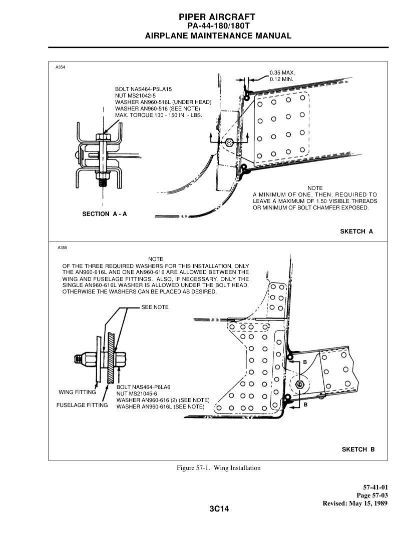
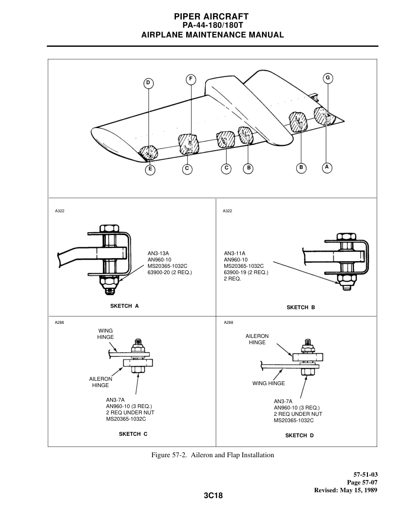
Right Wing Semi-tapered, all-metal cantilever wing with stressed skin and internal structural members.
Overview Total aircraft wingspan: 38 ft 6.6 in (supplied course specification). A bladder-type fuel cell is housed in each wing. The wing is semi-tapered; the external skin and supporting structure carry loads. Construction The wing structure incorporates a main spar and auxiliary front and rear spars. Ribs establish the airfoil profile and help distribute structural loads. The main spar joins the fuselage through the spar-box structure. Aerodynamics Stalls occur when the wing exceeds its critical angle of attack, not simply at one fixed indicated airspeed. A semi-tapered planform affects spanwise loading and potential stall progression, but taper alone does not determine where the stall begins. Use the approved PA-44 POH for actual stall speeds, configuration effects, warning behavior and recovery procedures. For a multiengine airplane, asymmetric thrust and loss of directional control can complicate slow flight and stall recovery. Source basis Supplied HTML cites PA-44 maintenance manual chapters 51, 55 and 57, the POH, and course material. Aircraft, manual revision, numeric limits, materials and emergency-exit details remain to be verified. See the canonical sources below. Aluminum alloy
Left Wing Left-side semi-tapered, all-metal cantilever wing.
Overview Contains a wing fuel bladder. Supports the left engine nacelle and left main landing gear assembly. Wingtip includes navigation/position lighting. Construction Stressed aluminum-alloy skin, spars, ribs and reinforcing members. Main spar and auxiliary front and rear spar structures. Aerodynamics The left and right wings are designed to operate as a matched pair. Stall progression depends on airfoil, twist, loading, surface condition and flight configuration. Refer to the POH for model-specific stall speeds and approved recovery procedures. Source basis Supplied HTML cites PA-44 maintenance manual chapters 51, 55 and 57, the POH, and course material. Aircraft, manual revision, numeric limits, materials and emergency-exit details remain to be verified. See the canonical sources below. Aluminum-alloy semi-monocoque
Fuselage The PA-44 fuselage uses riveted stressed skin supported by bulkheads, stringers and stiffeners.
Overview Cabin entry door is on the right side. The pilot-side left window and its surrounding frame form the emergency exit. The baggage compartment limit supplied in your training material is 200 lb; verify against the specific aircraft POH. Construction The external skin is structural and shares loads with the internal framework. Bulkheads and stringers reinforce the fuselage and distribute stresses. Aerodynamics Fuselage attitude and loading influence flight behavior, but the wing angle of attack is central to aerodynamic stall. Source basis Supplied HTML cites PA-44 maintenance manual chapters 51, 55 and 57, the POH, and course material. Aircraft, manual revision, numeric limits, materials and emergency-exit details remain to be verified. See the canonical sources below. Fiberglass fairing
Nose Cone Aerodynamic nose fairing ahead of the cabin.
Overview Smooths airflow around the forward fuselage. Distinct from the riveted primary aluminum structure. Construction The nose fairing is modeled as fiberglass, per your supplied course material. Aerodynamics The nose cone does not establish the wing’s critical angle of attack. Source basis Supplied HTML cites PA-44 maintenance manual chapters 51, 55 and 57, the POH, and course material. Aircraft, manual revision, numeric limits, materials and emergency-exit details remain to be verified. See the canonical sources below. Metal nacelle; steel engine mount
Left Engine Nacelle Wing-mounted housing surrounding the left engine.
Overview Engine is supported by a steel mounting structure. The nacelle and cowling provide aerodynamic enclosure and service access. Construction Steel engine mounting components transmit loads into the wing structure. Aerodynamics An engine failure can produce yaw and roll tendencies; follow the PA-44 approved engine-out procedures. Source basis Supplied HTML cites PA-44 maintenance manual chapters 51, 55 and 57, the POH, and course material. Aircraft, manual revision, numeric limits, materials and emergency-exit details remain to be verified. See the canonical sources below. Metal nacelle; steel engine mount
Right Engine Nacelle Wing-mounted housing surrounding the right engine.
Overview Engine mount uses steel components. Engine and nacelle loads are carried into the wing structure. Construction Removable cowling surrounds the engine installation. Aerodynamics Power asymmetry matters especially at low airspeeds; refer to POH limitations and procedures. Source basis Supplied HTML cites PA-44 maintenance manual chapters 51, 55 and 57, the POH, and course material. Aircraft, manual revision, numeric limits, materials and emergency-exit details remain to be verified. See the canonical sources below. All-metal semi-monocoque
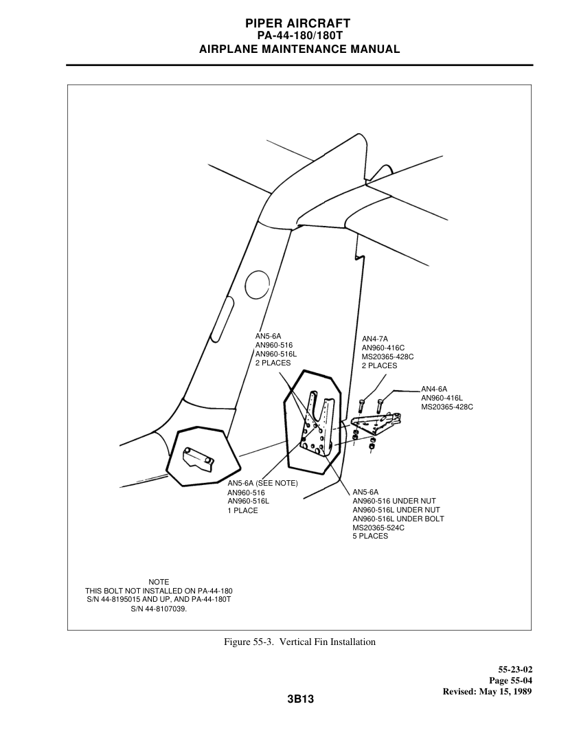
Vertical Tail / T-Tail Tall vertical fin supports the elevated horizontal stabilator.
Overview Distinctive PA-44 T-tail configuration. The rudder provides directional control. Construction The empennage is an all-metal cantilever semi-monocoque structure. Aerodynamics The stabilator is elevated above much of the normal propeller slipstream. At low airspeeds, pitch-control authority and required control forces can differ from a conventional low tail. Deep stall is a general T-tail aerodynamic concern; do not assume a particular PA-44 deep-stall characteristic without type-specific evidence. Source basis Supplied HTML cites PA-44 maintenance manual chapters 51, 55 and 57, the POH, and course material. Aircraft, manual revision, numeric limits, materials and emergency-exit details remain to be verified. See the canonical sources below. All-metal tail surface
Horizontal Stabilator High-mounted, movable horizontal tail surface on the T-tail.
Overview Provides pitch control. Mounted atop the vertical stabilizer. Construction Metal skin and internal supporting members. Aerodynamics Pitch control and stall behavior depend on airflow at the stabilator. Consult the approved POH for operating limitations and procedures. Source basis Supplied HTML cites PA-44 maintenance manual chapters 51, 55 and 57, the POH, and course material. Aircraft, manual revision, numeric limits, materials and emergency-exit details remain to be verified. See the canonical sources below. Transparent glazing and surrounding structure
Cabin Windows / Emergency Exit Cabin windows and pilot-side emergency exit.
Overview Primary entry door is on the right side. Pilot-side left window and frame provide an emergency exit. Brief passengers on the emergency release handle. Construction The window opening is integrated into the reinforced fuselage structure. Aerodynamics Not a stall-control component. Source basis Supplied HTML cites PA-44 maintenance manual chapters 51, 55 and 57, the POH, and course material. Aircraft, manual revision, numeric limits, materials and emergency-exit details remain to be verified. See the canonical sources below. Fiberglass fairings
Wing Tips Removable outer wingtip fairings.
Overview Aerodynamic end caps on each wing. Contain or adjoin navigation/position lighting. Construction Fiberglass material as listed in your course notes. Aerodynamics Wingtip shape affects local flow, but stall progression must be assessed for the complete wing design. Source basis Supplied HTML cites PA-44 maintenance manual chapters 51, 55 and 57, the POH, and course material. Aircraft, manual revision, numeric limits, materials and emergency-exit details remain to be verified. See the canonical sources below. Equipment-dependent antenna assemblies
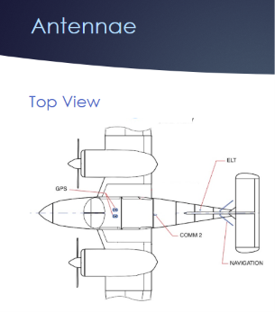
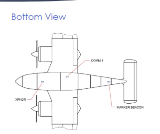
Antennas Locations are shown in the top and bottom diagrams supplied with your training materials.
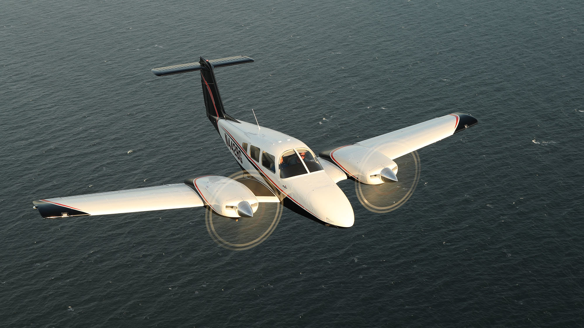
Overview Top view image: GPS, COMM 2, ELT and navigation antenna locations Bottom view image: COMM 1, transponder (XP NDR) and marker beacon antenna locations The diagrams represent the supplied aircraft configuration; actual installations can differ. Construction Antenna mounts and cabling integrate with the airframe and avionics system. Aerodynamics Antennas are not primary stall-related structures. Source basis Supplied HTML cites PA-44 maintenance manual chapters 51, 55 and 57, the POH, and course material. Aircraft, manual revision, numeric limits, materials and emergency-exit details remain to be verified. See the canonical sources below. Original aircraft photograph & component highlights The supplied photograph preserves the original highlight regions. Select a region or use the equivalent component list above. Highlight boundaries are approximate.
Open full-size supplied photograph Antenna guide · supplied top & underside diagrams The supplied diagrams label top-side GPS, COMM 2, ELT and navigation antennas; underside COMM 1, transponder and marker beacon antennas. Installation and text must be checked for the specific aircraft. The 3D model’s antenna is a generic illustration, not this installation map.
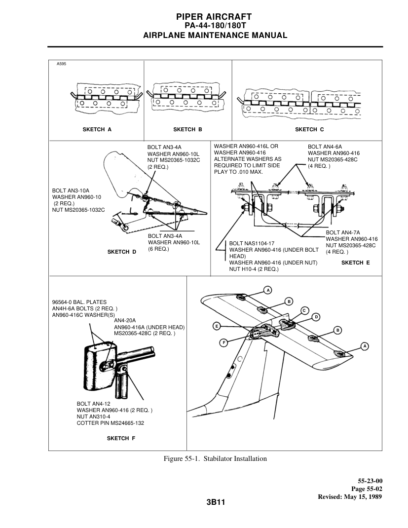
Construction reference figures Supplied maintenance-manual excerpts. Manual revision, applicability and reuse rights remain unverified.